Electricity Tutorial
This tutorial is a brief introduction to the concepts of charge, voltage, and current. This tutorial is not as long and tedious as a college textbook, yet it contains more information than students are likely to find in an elementary schoolbook.The Atom
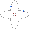 On the left is a conceptual drawing of an atom. Atoms are the building blocks of matter. Everything is made of atoms, from rocks, to trees, to stars, to even yourself. An atom consists of a tightly packed nucleus containing one or more protons (colored red in the picture), and usually an equal number of neutrons (gray). Electrons (blue) surround the nucleus, forming an electron cloud. The number of electrons in an electrically stable atom is always equal to the number of protons in the nucleus.
Electric Charge

 A curious thing happens between protons and electrons: a proton and an electron are always attracted to one another, while a proton will repel other protons, and an electron will repel other electrons. This behavior is caused by something called the electric force. Protons are said to have a positive electric charge, while electrons have a negative electric charge. Two objects with the same type of charge push away from each other, while two objects with opposite charges attract to each other. Since a proton and an electron have opposite electric charges, they are attracted to each other. Two protons, however, move away from each other because of their equal electric charges. The same is true of two electrons, which push away from each other because of their equal negative charges.
Electric Balance
 Most matter contains an equal number of protons and electrons. The negative electrons balance out the positive protons, and the matter has no overall electrical charge. The word overall is important, since the charges are still there, bouncing around inside the matter. Electrical charges are everywhere, but we just can't sense them because they are in balance. In fact, if you take chemistry, you'll learn that the electric force is the very thing that holds matter together. The next time you pick something up, just think that whatever you are holding is literally filled with electric charge. This is an important fact that many people miss when they study electricity.
Static Electricity
 Let's say we steal an electron from one atom and give the electron to another atom. One atom will have an overall positive charge and the other will have an overall negative charge. When this happens, the two atoms are called ions. Because ions have an overall electric charge, they can interact with other charged objects. Since like charges repel and opposite charges attract, a positive ion will attract negatively charged objects, such as electrons or other ions, and will repel positively charged objects. A negatively charged ion will attract positively charged objects, and will repel other negatively charged objects.
The same is true for larger objects. If you take electrons from one object and place them on another object, the first object will have an overall positive charge while the second will have an overall negative charge. Depending on the types of objects and the amount of charge involved, the electric force may be enough to cause the objects to stick together. This phenomenon is often referred to as "static electricity."
There are several ways to steal electrons from one object and give them to another. Some of the ways include chemical reactions, mechanical motion, light, and even heat. If you rub a glass rod with silk, the electrons in the glass rod will be knocked off and collected on the silk. The glass rod gains an overall positive charge, and the silk gains an overall negative charge. In a battery, chemical reactions are used to force electrons from the positive terminal and place them on the negative terminal.
Measuring Charges
The amount of overall electric charge possessed by an object is measured in coulombs. One coulomb is roughly equal to the amount of charge possessed by 6,000,000,000,000,000,000 (six billion billion) electrons. While this may seem like a huge number at first, it is not really that much, since electrons are so tiny. Just to give you an idea, one coulomb is roughly the amount of charge that flows through a 12-watt automotive light bulb in one second.If the amount of charge possessed by two objects and the distance between them are known, it is possible to calculate the amount of force between the objects using a formula known as Coulomb's law. This law was discovered by Charles Augustin de Coulomb in 1784, and states that the force between two charged objects varies directly as the charges of the objects and inversely as the square of the distance between them. Coulomb's law is given below in formula form:

F is the force, in Newtons.
q and q' are the charges of the two objects, in coulombs.
r is the distance between the objects, in meters.
k is a constant equal to 8.98755×10⁹ N m2 C-2
Voltage
Whenever electrons are taken from one object and placed on another object, causing an imbalance of charge, we say that a voltage exists. That is what somebody means when they say that something has so many volts of electricity. They are describing a difference of charge in two different places. A standard AA battery has a difference of 1.5 volts between its positive and negative terminal, while car battery has a difference of 12 volts between its two terminals, and the everyday type of static electricity that causes things to stick together and occasionally gives you a jolt when you touch a metal object is usually measured in thousands of volts. Another way to understand voltage is to think of an "electric field." Imagine a plate with positive charge next to a plate with negative charge. If I place a positive charge between these plates, the plates’ electric field will attract the charge to the negative side. Imagine that I place a 1 coulomb positive charge next to the negative plate, and then pull it towards the positive plate. Because the electric field creates a force in the opposite direction, moving the charge requires energy. The amount of energy depends on the distance between the plates and the strength of the electric field created by the plates. We call this energy the electric field’s "voltage." One volt is the amount of energy in joules required to move 1 coulomb of charge through an electric field. Mathematically, 1Volt = 1Joule / 1Coulomb.
Volts are useful, because they neatly describe the size and strength of any electric field. Visualizing the electric field between two simple plates is easy, but visualizing the field in a complicated circuit with batteries, motors, light bulbs, and switches is very difficult. Voltage simplifies circuits like these by describing the entire electric field with a single number.
Electric Current
 The word current comes from the Latin word currere, which means to run or to flow. An electric current is nothing more than the flow of electric charges. Electric charges can only flow through certain materials, called conductors. Although the electrons in most materials are confined to fixed orbits, some materials, including most metals, have many loose electrons which are free to wander around through the material. Materials with this property act as conductors. When a conductor is placed between two charged objects, these loose electrons are pushed away by the negatively charged object and are sucked into the positively charged object. The result is that there is a flow of charge, called a current, and the two object's charges become balanced. The amount of current flowing through a conductor at any given time in measured in amperes, or amps for short. When you read that something uses so many amps, what you are being told is the amount of current flowing through the device. One ampere is equal to the flow of one coulomb of charge in one second.
Batteries and Current
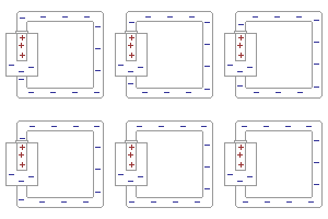 In the previous paragraph, we looked at how current flows from one charged object to another, canceling out the charges of the two objects. Once the charges were canceled, the current stopped. If current were always this short-lived, it would be very impractical. Imagine a flashlight that only lasted a fraction of a second before needing to be recharged! While current does tend to cancel out charges on two objects and then stop flowing, if a charge can be placed on the objects faster than the current can drain the charge, it is possible to keep a current flowing indefinitely. That is what happens in a battery. Chemical reactions within the battery pump electrons from the positive terminal to the negative terminal faster than the device connected to the battery can drain them. The battery will continue to supply as much current as the device requires until the chemicals within the battery are used up, at which point the battery is dead and must be replaced.
Resistance
All conductors offer some degree of resistance to the flow of electric current. What happens is this: As electrons travel through the conductor, they bump into atoms, losing some of their movement in jiggling the atom. The result is that the current flowing through the conductor is slowed down, and the conductor is heated. The amount that a given conductor resists the flow of electric current is measured in ohms.Power
Whenever current flows, work is done. A conductor may be heated, a motor may be spun, a bulb might give off light, or some other form of energy may be released. There is a simple law that tells exactly how much work may be done by a flowing current. The amount of work done is equal to the voltage of the supply times the current flowing through the wire. This law is expressed in the form P=IV, where P is the power in watts, I is the current in amps, and V is the voltage in volts. For example, if we find that a light bulb draws half of an amp at 120 volts, we simply multiply the 120 volts by half an amp to find that the bulb draws 60 watts of power.Ohm's Law
 Let's say you have a six volt battery and you need to draw two amps of current. What resistance should you make the conductor? Or let's say you have a three volt power supply and a thousand ohm resistor. How much current would flow through the resistor if you were to connect the resistor to the power supply? In order to find the answers to these questions, all you need to do is to use a simple mathematical formula called ohm's law. Ohm's law states that the amount of current flowing through a conductor times the resistance of the conductor is equal to voltage of the power supply. This law is often expressed in the form V=IR, where V is the voltage measured in volts, I is the current measured in amps, and R is the resistance measured in ohms.
electric circuit, unbroken path along which an electric current exists or is intended or able to flow. A simple circuit might consist of an electric cell (the power source), two conducting wires (one end of each being attached to each terminal of the cell), and a small lamp (the load) to which the free ends of the wires leading from the cell are attached. When the connections are made properly, current flows, the circuit is said to be “closed,” and the lamp will light. The current flows from the cell along one wire to the lamp, through the lamp, and along the other wire back to the cell. When the wires are disconnected, the circuit is said to be “open” or “broken.” In practice, circuits are opened by such devices as switches, fuses, and circuit breakers (see fuse, electric; circuit breaker; short circuit). Two general circuit classifications are series and parallel. The elements of a series circuit are connected end to end; the same current flows through its parts one after another. The elements of a parallel circuit are connected so that each component has the same voltage across its terminals; the current flow is divided among its parts. When two circuit elements are connected in series, their effective resistance (impedance if the circuit is being fed alternating current) is equal to the sum of the separate resistances; the current is the same in each component throughout the circuit. When circuit elements are connected in parallel, the total resistance is less than that of the element having the least resistance, and the total current is equal to the sum of the currents in the individual branches. A battery-powered circuit is an example of a direct-current circuit; the voltages and currents are constant in magnitude and do not vary with time. In alternating-current circuits, the voltage and current periodically reverse direction with time. A standard electrical outlet supplies alternating current. Lighting circuits and electrical machinery use alternating current circuits. Many other devices, including computers, stereo systems, and television sets, must first convert the alternating current to direct current. That is done by a special internal circuit usually called a power supply. A digital circuit is a special kind of electronic circuit used in computers and many other devices. Magnetic circuits are analogous to electric circuits, where magnetic materials are regarded as conductors of magnetic flux. Magnetic circuits can be part of an electric circuit; a transformer is an example. Equivalent circuits are used in circuit analysis as a modeling tool; a simple circuit made up of a resistor, and an inductor might be used to electrically represent a loudspeaker. Electrical circuits can also be used in other fields of studies. In the study of heat flow, for example, a resistor is used to represent thermal insulation. Operating electric circuits can be used for general problem solving (as in an analog computer).
| Kirchhoff's laws |
Kirchhoff's laws [for Gustav R. Kirchhoff], pair of laws stating general restrictions on the current and voltage in an electric circuit. The first of these states that at any given instant the sum of the voltages around any closed path, or loop, in the network is zero. The second states that at any junction of paths, or node, in a network the sum of the currents arriving at any instant is equal to the sum of the currents flowing away.

| inductance |
inductance, quantity that measures the electromagnetic induction of an electric circuit component; it is a property of the component itself rather than of the circuit as a whole. The self-inductance, L, of a circuit component determines the magnitude of the electromagnetic force (emf) induced in it as a result of a given rate of change of the current through the component. Similarly, the mutual inductance, M, of two components, one in each of two separate but closely located circuits, determines the emf that each may induce in the other for a given current change. Inductance is expressed in henrys (for Joseph Henry). An inductor is a device designed to produce an inductance, e.g., a coil; an ideal inductor, i.e., one having no resistance or capacitance (see impedance), is often called an inductance.
Hukum Ohm menyatakan bahwa besar arus yang mengalir pada suatu konduktor pada suhu tetap sebanding dengan beda potensial antara kedua ujung-ujung konduktor
E = ggl (volt) rd = hambatan dalam elemen R = hambatan luar p = banyaknya elemen yang disusun paralel RANGKAIAN HAMBATAN DISUSUN SERI DAN PARALEL
ENERGI LISTRIK (W) adalah energi yang dipakai (terserap) oleh hambatan R. W = V I t = V²t/R = I²Rt Joule = Watt.detik KWH = Kilo.Watt.jam DAYA LISTRIK (P) adalah energi listrik yang terpakai setiap detik. P = W/t = V I = V²/R = I²R | |||||||||
S Iin = Iout
Se = S IR = 0
ALAT UKUR LISTRIK TERDIRI DARI| 1. JEMBATAN WHEATSTONE | digunakan untuk mengukur nilai suatu hambatan dengan cara mengusahakan arus yang mengalir pada galvanometer = nol (karena potensial di ujung-ujung galvanometer sama besar). Jadi berlaku rumus perkalian silang hambatan : R1 R3 = R2 Rx |
| 2. AMPERMETER | untuk memperbesar batas ukur ampermeter dapat digunakan hambatan Shunt (Rs) yang dipasang sejajar/paralel pada suatu rangkaian. Rs = rd 1/(n-1) n = pembesaran pengukuran |
| 3. VOLTMETER | untuk memperbesar batas ukur voltmeter dapat digunakan hambatan multiplier (R-) yang dipasang seri pada suatu rangkaian. Dalam hal ini R. harus dipasang di depan voltmeter dipandang dari datangnya arus listrik. Rm = (n-1) rd n = pembesaran pengukuran |
adalah beda potensial antara kutub-kutub sumber atau antara dua titik yang diukur.
1. Bila batere mengalirkan arus maka tegangan jepitnya adalah:
| Vab = e - I rd |
| Vab = e + I rd |
tegangan jepitnya adalah .
| Vab = e |
Dalam menyelesaian soal rangkaian listrik, perlu diperhatikan :
1. Hambatan R yang dialiri arus listrik. Hambatan R diabaikan jika tidak
dilalui arus listrik.
2. Hambatan R umumnya tetap, sehingga lebih cepat menggunakan
rumus yang berhubungan dengan hambatan R tersebut.
3. Rumus yang sering digunakan: hukum Ohm, hukum Kirchoff, sifat
rangkaian, energi dan daya listrik.
Contoh 1 :
Untuk rangkaian seperti pada gambar, bila saklar S1 dan S2 ditutup maka hitunglah penunjukkan jarum voltmeter !
Jawab :
Karena saklar S1 dan S2 ditutup maka R1, R2, dan R3 dilalui arus listrik, sehingga :
| 1 = 1 + 1 Rp R2 R3 Rp = R2 R3 = 2W R2 + R1 V = I R = I (R1 + Rp)I = 24/(3+2) = 4.8 A |
V = I2 R2 = I3 R3 = I Rp
V = I Rp = 0,8 V
Contoh 2:
Pada lampu A dan B masing-masing tertulis 100 watt, 100 volt. Mula-mula lampu A den B dihubungkan seri dan dipasang pada tegangan 100 volt, kemudian kedua lampu dihubungkan paralel dan dipasang pada tegangan 100 volt. Tentukan perbandingan daya yang dipakai pada hubungan paralel terhadap seri !
| Hambatan lampu dapat dihitung dari data yang tertulis dilampu : RA = RB = V²/P = 100²/100 = 100 W Untuk lampu seri : RS = RA + RB = 200 W Untuk lampu paralel : Rp = RA × RB = 50 W RA + RB |
Jadi perbandingan daya paralel terhadap seri adalah :
Pp = V² : V² = Rs = 4
Ps Rp Rs Rp 1
Contoh 3:
Dua buah batere ujung-ujungnya yang sejenis dihubungkan, sehingga membentuik hubungan paralel. Masing-masing batere memiliki GGL 1,5 V; 0,3 ohm dan 1 V; 0,3 ohm.Hitunglah tegangan bersama kedua batere tersebut !
Jawab :
Tentakan arah loop dan arah arus listrik (lihat gambar), dan terapkan hukum Kirchoff II,
| Se + S I R = 0 e1 + e2 = I (r1 + r2) I = (1,5 - 1) = 5 A 0,3 + 0,3 6 |
Vab = e1 - I r1 = 1,5 - 0,3 5/6 = 1,25 V
1= e2 + I R2 = 1 + 0,3 5/6 = 1,25 V
Contoh 4:
Sebuah sumber dengan ggl = E den hambatan dalam r dihubungkan ke sebuah potensiometer yang hambatannya R. Buktikan bahwa daya disipasi pada potensiometer mencapai maksimum jika R = r.
Jawab :
| Dari Hukum Ohm : I = V/R = e R+r Daya disipasi pada R : P = I²R = e ²R (R+r)² |
Jadi e² (R+r)² - E² R.2(R+r) = 0
(R+r)4
e² (R+r)² = e² 2R (R+r) Þ R + r = 2R
R = r (terbukti)
ARUS/TEGANGAN BOLAK-BALIK
Arus/tegangan bolak-balik adalah arus/tegangan yang besarnya selalu berubah-ubah secara periodik. Simbol tegangan bolak-balik adalah ~ dan dapat diukur dengan Osiloskop (mengukur tegangan maksimumnya).
NILAI EFEKTIF KUAT ARUS/TEGANGAN AC
Nilai efektif kuat arus/tegangan AC adalah arus/tegangan AC yang dianggap setara dengan kuat arus/tegangan AC yang menghasilkan jumlah kalor yang sama ketika melalui suatu penghantar dalam waktu yang sama.
Kuat arus efektif : Ief = Imaks / Ö2
Tegangan efektif : Vef = Vmaks / Ö2
Besaran yang ditunjukkan oleh voltmeter/amperemeter DC adalah tegangan/kuat arus DC yang sesungguhnya,sedangkan yang ditunjukan oleh voltmeter/amperemeter AC adalah tegangan/kuat arus efektif, bukan tegangan/kuat arus sesungguhnya.


