Deaeration of Condensate and Make-up Water
in Steam Turbine and Combined Cycle Power Plants
High oxygen content in the feedwater can cause corrosion of components and piping. The deaerator should be designed to remove the maximum amount of the incondensable gases possible from the boiler feedwater cycle and to achieve an oxygen content of < 7 ppb (=0.005 cc/l) in the feedwater. This protects the boiler and the whole system against corrosion. Depending on the pressure in the feed water tank/deaerator the deaeration process takes place either under vacuum (known as vacuum deaeration) at about 60°C, 0.2 bar, or at pressure above atmospheric pressure (over-pressure deaeration).Deaeration of Condensate
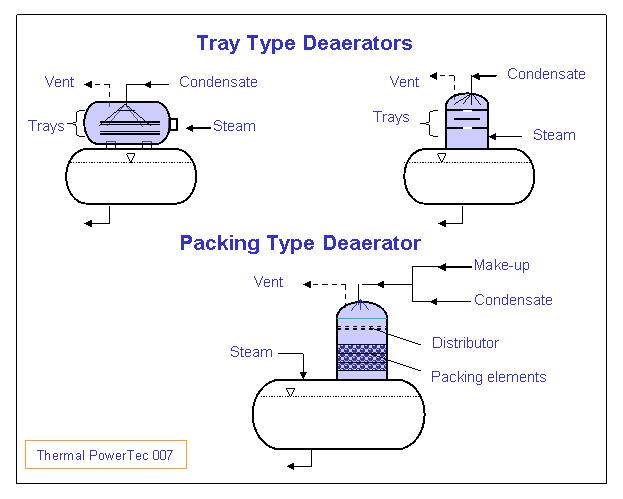
If the oxigen content of condensate at the deaerator inlet is not very high, a tray type deaerator can be used (see deaerators Fig. 007).
Tray Type Deaerators:
- Tray type deaerator as horizontal vessel over FWST
- Annular tray type deaerator as vertical dome over FWST (ALSTOM tray type Deaerator)
- Tray type deaerator as vertical dome over FWST (TPT tray type Deaerator).
The water is sprayed at the top of deaerator by means of a spring-operated sprayer or by means of spray nozzles. The sprayer reduced the water to small droplets or to a water film. The water flows down between trays or deflection baffles. The steam enters the deaerator in the lower part of the deaerator and rises to the sprayed water in counterflow to the down-coming water and takes away the gases from the water. The steam condenses practically on the sprayed water and the incoming water is heated to the satturation temperature and deaerated. The apparatus works as DC heater and deaerator.
The freed oxygen is discharged to atmosphere or to the condenser via the vent openings at deaerator top, which may be fitted with throttling organ.
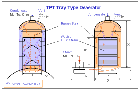
Inlet condensate: Flow rate Mc, Temperature Tc, oxygen content C1o2
Steam flow rate Ms: Ms = f(Mc, Tc, Ps)
Dome diameter D: D = f(Mc, Ms, Ps)
Bypass steam channel ratio: L/D = f(Ms, Ps)
Venting flow rate Mvent: Mvent = f(Mc, C1o2, C2o2)
Deflection plats number (baffles) and height H1 are function of O2 content C1o2, C2o2 and Ps.
Design of the TPT Deaerator:The deaerator is laid out in such a way that the main heating steam flows through two by-pass channels and the condensate and flush steam are connected in a counter flow.For the design of a deaerator the following condensate and steam load capacities are computed:
a) Water load capacity
The water load capacity limit (flood limit) is put at the basis for the maximum condensate mass flow density mc (kg/sm2) through the deaerator dome.
Since steam in the top of the dome condensed and the condensate increases the water load of the deaerator qross-section, for the diameter definition the mass flow density mc is computed from the sum of the condensate flow (Mc) and the steam flow (Ms).
b) Steam load capacity
The load capacity limit (flood limit) for a given deaerator type is a function of the steam flow and the steam pressure or the density of the saturated steam.
With an excess of the Steam load capacity instability with strong steam impacts will arise.
The deaerator masses (dome diameter D, by-pass steam chanels or their distance L, ...) are laid out so that the flood limit is not exceeded. The calculation will be determined for the worst operation case and from the water and steam load capacities of the deaerator (see deaerator sketch 007a).
Deaeration of Make-up Water
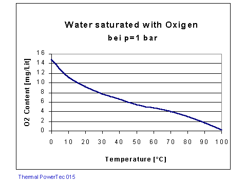
Make-up water is usually fully saturated with oxygen (see diagram).
For make-up water with oxygen content of 9000 ppb (9 mg/lit) at deaerator inlet, the oxygen content at the outlet of 5 to 7 ppb (0.005 to 0.007 mg/lit) should be achieved.
For a lower mass flow rate of make-up the water can be sprayed to the cycle in the condenser neck.
For make-up water with oxygen content of 9000 ppb (9 mg/lit) at deaerator inlet, the oxygen content at the outlet of 5 to 7 ppb (0.005 to 0.007 mg/lit) should be achieved.
For a lower mass flow rate of make-up the water can be sprayed to the cycle in the condenser neck.

Packing Deaerator
for Make-up Water and Condensate
The deaerator is arranged as cylindrical dome over FWST or as separate deaerator. The mixture of Make-up water and condensate is sprayed at the top of the deaerator (Fig. 007). By means of a distributor the sprayed water is distributed across the dome cross-section. The water trickles down through the mass transfer packing elements and forming a large interfacial area between the water and the surrounding steam phase. A venting system extracts all gases from the vapor phase. The freed non-condensable gases is discharged to atmosphere or to the condenser via the vent openings at deaerator top.
Since the packing elements are expensive, the packing deaerator is used for deaeration of water under extreme parameters (high oxygen content and low pressure).
The disadvantage of this deaerator type (especially in case of vacuum deaeration) that a large packing diameter is necessary because of the large volume flow of the heating steam. The large packing volume leads to higher deaerator costs.
TPT Packing Deaerator
for make-up water and condensate
High performance deaerator for high make-up flow rate and vacuum pressure
The Make-up water is sprayed in a chamber at the top of the deaerator dome. During direct introduction of steam to the upper chamber the water is heated and partly deaerated. The heated water flows downward to the distributor and distributed across the dome cross-section (Fig. 007b).
The condensate can be introduced into the dome by spray nozzles above the Packing or by a spraying valve above the distributor. The make-up water and the condensate trickle down through the packing elements in counter flow to the second steam flow part.
The steam flow through the packing is reduced and thus arises a small packing diameter.
The packing diameter D is laid out so that the flood limit is not exceeded. The calculation will be determined for the worst operation case and from the water and steam load capacities of the deaerator.
Venting System:
By means of a venting system with a venting condenser the gases is extracted from the deaerator through several venting stages. A small bypass make-up flow is selected, which is sprayed by a small nozzle into the vent condenser. By means of openings at the top of the upper chamber and the top of the packing chamber the steam/air flows (Vent 1 and Vent 2) are throttled to the vent condenser. The throttle organs of the vent lines 1 and 2 are adjusted in such a way that the pressure Pv of the vent condenser and the desired steam/air flows (Vent 1 and Vent 2) results in. The non-condensable gases (Vent Mv) is discharged from the vent condenser via a throttle organ to the condenser.
Special Packing Deaerators for CCPP:
Patent: EP 077500: Packing Deaerator with counter-flow
Patent: US 5203286: Packing Deaerator with parallel/counter-flow


Tidak ada komentar:
Posting Komentar