Heat Exchangers
Optimization of thermodynamic design
LP Feedwater Heaters, Didtrict Heaters and Duplex Heaters
HP Feadwater Heaters of tubesheet and header type
Water/water Coolers
Heat exchangers are especially handled by TPT.
In the tubesheet FWHs the tube bundle consists of bend tubes of U-form and the tubes are connected to the tubesheet. Th FWHs are arranged as vertical or horizontal heaters.
Tubes and tube bundle carrier:
( Patent: tube bundle carrier)(tube bundle carrier)
The tube material, tube diameter and water velocity are selected for the feed water heaters according to operational safety and economy. The tubes are expanded by rolling into the tube sheet. The bundle carrier is designed such that the tubes are protected against deformation and vibration and can freely expand. The support plates with the tube bundles can freely move in longitudinal and cross direction despite the unequal thermal expansion due to the hot and cold tube leg. The support plates show furthermore supports in the shape of wings in order for lateral guidance of the bundle carrier at the inner wall of the steam shell. The bundle carrier consists of support plates, side metal sheets, spacers and tie-rods which can be quickly assembled with little welding work and economically.
LP Feedwater Heater:
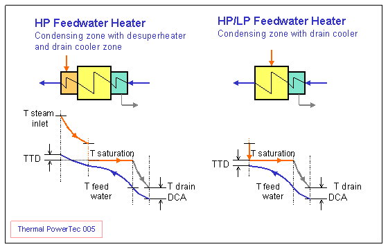
LP FWHs are designed as single zone with a condensing section or two zones with a condensing section and integral subcooler section. Drain coolers are employed because of heat consumption improvement in case of drain introduction into the lower heater through the level control valve.
Condensing heaters without subcooler section have a better heat consumption if the drain flows forward by using a drain pump. A drain pump is used usually for the drain of LP heaters No. 2 and 4.
HP Feedwater Heater:
( Patent AU 1404792: HP Feedwater Heater)
Tubesheet HP heaters are designed as two zones or three zones with condensing section, desuperheater and integral subcooler.The use of a desuperheater reduces the terminal temperature difference (TTD) of the entire FWH. A negative TTD can be achieved by the use of a desuperheater. The limit of the theoretically possible desuperheating of steam is given by the condition of the still dry outer wall of the tube at the outlet of the desuperheater. The tube wall temperature must be over the local saturation temperature in all operation conditions.
The use of a separate cross-connected desuperheater improves the heat consumption and increases the feedwater temperature at the boiler inlet.
Drain coolers are employed because of heat consumption improvement in case of drain introduction into the lower heater through the control valve.
Header Type FWH:
These type of HP FWH has been developed to meet the increasingly severe operating conditions in large turbogenerator plants. These may include high heat rates, sudden load variations and frequent start-ups and shut-downs in case of peak-load power plants. The header type Heaters have lower maximum stresses during transient operating condition and therefore fewer potential failure mechanisms than tubesheet heaters. The tube bundle consists of multiple bend tubes and the tubes are connected to the thick-walled headers by means nipples.
For more information on Header Type FWH see:
"Header Type FW Heater as Retrofit for Cycling Units"
Dr. M. Youssef, Power-Gen Europe 93: Mai 25-27, 1993 Paris
Heat flow in:
Desuperheater section 3 Condensing section 2 Subcooler section 1
Q3=Mw x(hw3o -hw3i) , Q2=Mw x(hw2o -hw2i) , Q1=Mw x (hw1o -hw1i) [kW]
Q3=Mst x(hs3i -hst3o) , Q2=Mst x(hs2i -hc2o) , Q1=Mcon x(hc1i -hc1o) [kW]
Heating area:
Ash =Qsh/(k3 . dTlog3) , Acon=Qcon/(k2 . dTlog2) , Asc =Qsc/(k1 . dTlog1) [m2]
Heat transfer coeffitient k: k3, k2 and k1 [kW/m2K]
Log. temperature difference: dTlog3, dTlog2 and dTlog1 [K]
Duplex Heaters:
( Patent: Duplex FW Heater)
( Duplex FW Heater)
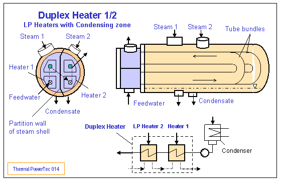
Duplex feed water heaters for a steam power plant are arranged horizontal and normally are inserted into the condenser neck. A duplex heater consists of two heat exchanger modules (LP Heater 1/ LP Heater 2) in a common shell. The Modules are applied as pure condensing heat exchanger modules or with a condensing zone and with an integral drain cooler. The two heater spaces are defined through a partition wall in the shell and turbine extraction steam of different pressure and temperature is fed via inlet nozzles. The water to be heated flows from the water box through the U-tubes of the first heat exchanger module while the extraction steam with the pressure P1 condenses on the outer surface of the tubes. The water heated in heater 1, flows through the U-tubes of the second heat exchanger module and is further heated through the extraction steam with the pressure P2 (P2>P1) and flows again into the water box to the outlet nozzle.The condensate is discharged at the bottom through two or more nozzles. The condensate flow of heater 2 is controlled through a control valve which controls the levels in the heat exchanger space 2. At a heat exchanger module with an integral drain cooler zone a flooded sectional bundle is chosen. The condensate of heater 1 flows via a siphon into the condenser.
Non condensing gases are sucked off over venting tubes which are positioned in the bundle lane at the zones of the lowest pressure.
The flows in the water box are achieved through the dividing the water box into three spaces by means of two internal shrouds or angular plates. The water box inlet nozzle is connected with the first shroud and the water outlet nozzle with the second shroud. Between both shrouds the feed water flows from heater 1 to heater 2.
The heat exchanger spaces are defined through a partition wall in the shell. The partition wall is carried out to a major part as a double-wall to provide insulation. Thereby the first wall which faces the heat exchanger space with the higher pressure is pressure bearing and the second wall which faces the heat exchanger space with the lower pressure serves as heat insulation and manufactured of thin sheet metal. For transmitting the force between the two walls thin metal sheets are provided. The space between the two walls is open through a number of holes at the bottom of the wall to the steam space with the lower pressure P1. The insulation provides a reduction in the heat loss flow and a power saving.
The load resulting from the pressure difference at the partition wall is transmitted via the support plates of heater 1 to the steam shell. The flexibility and the support of the partition wall avoid excessive stress at the connection place shell-partition wall due to heat expansion and over bending.
District Heaters:
District heaters (DHs) are built as condensing heat exchangers or with an integral drain cooler zone. DHs are designed for horizontal or vertical instalation. DHs are tubesheet type tubebundle heat exchangers with straight or U-tubes. The tubes are expanded into the tubesheet. By means of support plates the tube bundle are protected against harmful vibrations.
The steam flow is distributed over the entire bundle across an annular space between the shell and the tubebundle. The heating water flows through the heat exchanger tubes, while the extracted steam condenses on the outer surfaces of the tubes. The condensate accumulats in the heater hotwell. The incondensible gases are extracted over the bundle length in the zones of lowest pressure. A sufficient venting provides a good heat transfer coefficients for assuring a maximum utilization of the installed heat transfer surfaces. The tube bundle is usually protected against erosion due to high velociy at the steam inlet nozzle by an impingement plate.
Water/Water Coolers:( Patent: Condenser with integral water cooler)
( Condenser with integral water cooler)
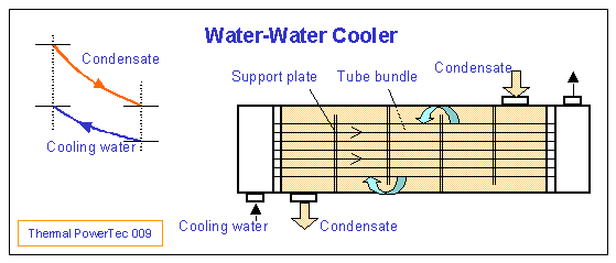
The water-water coolers are used for back cooling of water or condensate of cooling cycle and are arranged near the condenser. Water-water coolers (WWCs) are designed for horizontal instalation. WWCs are tubesheet type tubebundle heat exchangers with straight tubes and with one or two passes. The tubes are expanded into the tubesheet.
The cooling water inter the waterbox and flows through the heat exchanger tubes (tube side, cold side), while the water to be cooled, here called condensate (shell side, warm side) flows on the outer surfaces of the tubes. By means of support plates the condensate is deflected in counter cross flow to the cooling water and the tube bundle are protected against harmful vibrations.
Failures of HP Feedwater Heater Tubes:
The tube failure is one of the major causes of forced outages in fossil fired power plants. The causes of these failures are related to design problems, fabrication problems and operational problems. These basic problems can result in various types of damage to heater tubes. For example, design problems are related to high velocity in tubes, vibration, material selection, and tube to tube sheet joint. Problems related to fabrication include support plate drilling, welds, tube to tubesheet joint fabrication. Operational problems are related to cycling, startup, lay-up, low load operation, operation with excessive flow, flow out of leaking tubes, water chemistry etc. These problems result in a variety of damages to the feedwater heater tubes.
The top of problem are
- Steam impingement in desuperheat and condensing zone
- Tube vibration caused by high cross-velocity
Tube failures in a heater can be avoided by a well-planned inspection. Inspections during planned outages and inspections during forced outages.
Failures in desuperheater
Failures can occur in desuperheater and cause damages
- Damage caused by steam condensation at the desuperheater outlet
- High inlet steam velocity
- Tube vibration caused by high steam cross-velocity
- Damage at the desuperheater outlet due to interaction of condensate and steam flow
Failure in subcooler
- Excessive condensate velocities lead to local flashing of the condensate and subsequent collapse of the vapour bubbles, which is harmful when this agitation occurs close to tubes or other erosion-corrosion prone materials.
- Tube vibration caused by high condensate cross-velocity


Tidak ada komentar:
Posting Komentar