

Ada aplikasi di mana band tertentu, atau menyebarkan, atau frekuensi harus disaring dari jangkauan yang lebih luas dari sinyal campuran. Filter circuits can be designed to accomplish this task by combining the properties of low-pass and high-pass into a single filter. Filter sirkuit dapat didesain untuk menyelesaikan tugas ini dengan menggabungkan sifat-sifat low-pass dan tinggi masuk ke filter tunggal. The result is called a band-pass filter. Hasilnya disebut band-pass filter. Creating a bandpass filter from a low-pass and high-pass filter can be illustrated using block diagrams: (Figure below ) Membuat filter bandpass dari lulus-rendah dan yang tinggi-pass filter dapat digambarkan menggunakan diagram blok: (Gambar di bawah ini )
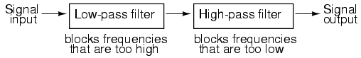
System level block diagram of a band-pass filter. Tingkat sistem blok diagram dari band-pass filter.
What emerges from the series combination of these two filter circuits is a circuit that will only allow passage of those frequencies that are neither too high nor too low. Apa yang muncul dari kombinasi seri dari dua rangkaian filter adalah sirkuit yang hanya akan memungkinkan bagian dari frekuensi yang tidak terlalu tinggi atau terlalu rendah. Using real components, here is what a typical schematic might look like Figure below . Menggunakan komponen nyata, di sini adalah apa yang khas skematis dapat terlihat seperti Gambar di bawah ini . The response of the band-pass filter is shown in (Figure below ) Tanggapan dari band-pass filter ditampilkan dalam (Gambar di bawah ini )

Capacitive band-pass filter. Capacitive band-pass filter.
capacitive bandpass filter kapasitif bandpass filter
v1 1 0 ac 1 sin v1 1 0 1 ac dosa
r1 1 2 200 r1 1 2 200
c1 2 0 2.5u c1 2 0 2.5u
c2 2 3 1u c2 2 3 1u
rload 3 0 1k rload 3 0 1k
.ac lin 20 100 500 ac lin. 20 100 500
.plot ac v(3) plot v ac (3.)
.end . Akhir

The response of a capacitive bandpass filter peaks within a narrow frequency range. Respon dari puncak filter bandpass kapasitif dalam rentang frekuensi sempit.
Band-pass filters can also be constructed using inductors, but as mentioned before, the reactive “purity” of capacitors gives them a design advantage. Band-pass filter juga dapat dibangun dengan menggunakan induktor, tapi seperti yang disebutkan sebelumnya, kemurnian "reaktif" kapasitor memberikan mereka keuntungan desain. If we were to design a bandpass filter using inductors, it might look something like Figure below . Jika kita mendesain filter bandpass menggunakan induktor, mungkin terlihat seperti Gambar di bawah ini .
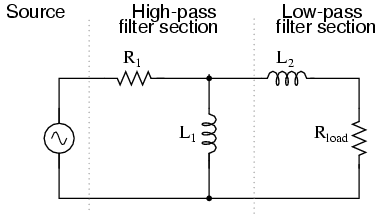
Inductive band-pass filter. Induktif band-pass filter.
The fact that the high-pass section comes “first” in this design instead of the low-pass section makes no difference in its overall operation. Kenyataan bahwa bagian bernilai tinggi datang "pertama" dalam desain bukan bagian low-pass ada bedanya beroperasi secara keseluruhan. It will still filter out all frequencies too high or too low. Ia masih akan menyaring semua frekuensi terlalu tinggi atau terlalu rendah.
While the general idea of combining low-pass and high-pass filters together to make a bandpass filter is sound, it is not without certain limitations. Sedangkan gambaran umum tentang menggabungkan low-pass dan high-pass filter sama untuk membuat sebuah filter bandpass adalah suara, itu bukan tanpa batasan tertentu. Because this type of band-pass filter works by relying on either section to block unwanted frequencies, it can be difficult to design such a filter to allow unhindered passage within the desired frequency range. Karena jenis ini band-pass filter bekerja dengan mengandalkan pada kedua bagian untukmemblokir frekuensi yang tidak diinginkan, bisa sulit untuk merancang filter seperti untuk memungkinkan tanpa hambatan bagian dalam rentang frekuensi yang diinginkan. Both the low-pass and high-pass sections will always be blocking signals to some extent, and their combined effort makes for an attenuated (reduced amplitude) signal at best, even at the peak of the “pass-band” frequency range. Kedua bagian low-pass dan bernilai tinggi akan selalu memblokir sinyal hingga batas tertentu, dan usaha bersama mereka untuk membuat amplitudo (dilemahkan dikurangi) sinyal pada terbaik, bahkan pada puncak band "-pass" rentang frekuensi. Notice the curve peak on the previous SPICE analysis: the load voltage of this filter never rises above 0.59 volts, although the source voltage is a full volt. Perhatikan puncak kurva pada analisis SPICE sebelumnya: tegangan beban filter ini tidak pernah naik di atas 0,59 volt, walaupun sumber tegangan adalah volt penuh. This signal attenuation becomes more pronounced if the filter is designed to be more selective (steeper curve, narrower band of passable frequencies). Peredaman sinyal ini menjadi lebih jelas jika filter ini dirancang untuk lebih selektif (kurva curam, band frekuensi yang dilalui sempit).
There are other methods to achieve band-pass operation without sacrificing signal strength within the pass-band. Ada metode lain untuk mencapai operasi band-pass tanpa mengorbankan kekuatan sinyal dalam band-pass. We will discuss those methods a little later in this chapter. Kita akan membahas metode-metode sedikit kemudian dalam bab ini.
- REVIEW: TINJAUAN:
- A band-pass filter works to screen out frequencies that are too low or too high, giving easy passage only to frequencies within a certain range. Sebuah band-pass filter berfungsi untuk menyaring frekuensi yang terlalu rendah atau terlalu tinggi, memberi jalan mudah hanya untuk frekuensi dalam kisaran tertentu.
- Band-pass filters can be made by stacking a low-pass filter on the end of a high-pass filter, or vice versa. Band-pass filter dapat dibuat dengan susun filter low-pass di ujung filter bernilai tinggi, atau sebaliknya.
- “Attenuate” means to reduce or diminish in amplitude. "Gepeng" berarti untuk mengurangi atau mengurangi amplitudo. When you turn down the volume control on your stereo, you are “attenuating” the signal being sent to the speakers. Ketika Anda menolak kontrol volume pada stereo Anda, Anda adalah "pelemahan" sinyal yang dikirim ke speaker.
FILTER- HIGH PASS
tugas Sebuah penyaring bernilai tinggi adalah hal yang berlawanan dari low pass filter-: menawarkan jalan yang mudah sinyal frekuensi tinggi dan bagian sulit sinyal frekuensi rendah. As one might expect, the inductive (Figure below ) Sebagai salah satu bisa diperkirakan, Gambar (induktif di bawah ini ) and capacitive (Figure below ) versions of the high-pass filter are just the opposite of their respective low-pass filter designs: dan kapasitif (Gambar bawah ) versi-pass filter tinggi hanya kebalikan dari masing-masing desain low-pass filter:

Capacitive high-pass filter. Kapasitif tinggi-pass filter.
The capacitor's impedance (Figure above ) Kapasitor's impedansi (Gambar di atas ) increases with decreasing frequency. meningkat dengan frekuensi menurun. (Figure below ) This high impedance in series tends to block low-frequency signals from getting to load. (Gambar di bawah ) ini impedansi tinggi dalam seri cenderung untuk memblokir sinyal frekuensi rendah dari sampai ke beban.
capacitive highpass filter kapasitif highpass filter
v1 1 0 ac 1 sin v1 1 0 1 ac dosa
c1 1 2 0.5u c1 1 2 0.5u
rload 2 0 1k rload 2 0 1k
.ac lin 20 1 200 ac lin. 20 1 200
.plot ac v(2) plot v ac (2.)
.end . Akhir

The response of the capacitive high-pass filter increases with frequency. Tanggapan kapasitif bernilai tinggi meningkat filter dengan frekuensi.

Inductive high-pass filter. Induktif tinggi-pass filter.
The inductor's impedance (Figure above ) Induktor's impedansi (Gambar di atas ) decreases with decreasing frequency. menurun dengan frekuensi menurun. (Figure below ) This low impedance in parallel tends to short out low-frequency signals from getting to the load resistor. (Gambar di bawah ) ini secara paralel impedansi rendah cenderung rendah dari frekuensi sinyal pendek dari mendapatkan ke resistor beban. As a consequence, most of the voltage gets dropped across series resistor R 1 . Akibatnya, sebagian besar tegangan yang akan turun di seri resistor R 1.
inductive highpass filter induktif highpass filter
v1 1 0 ac 1 sin v1 1 0 1 ac dosa
r1 1 2 200 r1 1 2 200
l1 2 0 100m l1 2 0 100m
rload 2 0 1k rload 2 0 1k
.ac lin 20 1 200 ac lin. 20 1 200
.plot ac v(2) plot v ac (2.)
.end . Akhir

The response of the inductive high-pass filter increases with frequency. Tanggapan induktif bernilai tinggi meningkat filter dengan frekuensi.
This time, the capacitive design is the simplest, requiring only one component above and beyond the load.Kali ini, desain kapasitif adalah sederhana, hanya membutuhkan satu komponen di atas dan di luar beban.And, again, the reactive purity of capacitors over inductors tends to favor their use in filter design, especially with high-pass filters where high frequencies commonly cause inductors to behave strangely due to the skin effect and electromagnetic core losses. Dan, sekali lagi, kemurnian reaktif kapasitor induktor cenderung lebih mendukung penggunaannya dalam desain filter, terutama dengan tinggi-pass filter di mana frekuensi tinggi sering menyebabkan induktor untuk berperilaku aneh karena pengaruh kulit dan kerugian inti elektromagnetik.
As with low-pass filters, high-pass filters have a rated cutoff frequency , above which the output voltage increases above 70.7% of the input voltage. Seperti-pass filter rendah,-pass filter tinggi memiliki frekuensi cutoff rate, yang meningkat di atas tegangan output di atas 70,7% dari tegangan input. Just as in the case of the capacitive low-pass filter circuit, the capacitive high-pass filter's cutoff frequency can be found with the same formula: Seperti halnya dalam kasus rangkaian low-pass filter kapasitif, frekuensi cutoff filter kapasitif bernilai tinggi dapat ditemukan dengan rumus yang sama:

In the example circuit, there is no resistance other than the load resistor, so that is the value for R in the formula. Pada rangkaian contoh, tidak ada perlawanan selain resistor beban, sehingga adalah nilai untuk R dalam rumus.
Using a stereo system as a practical example, a capacitor connected in series with the tweeter (treble) speaker will serve as a high-pass filter, imposing a high impedance to low-frequency bass signals, thereby preventing that power from being wasted on a speaker inefficient for reproducing such sounds.Menggunakan sistem stereo sebagai contoh praktis, kapasitor yang terhubung secara seri dengan tweeter (treble) pembicara akan berfungsi sebagai penyaring bernilai tinggi, memberlakukan impedansi tinggi untuk sinyal bass frekuensi rendah, sehingga mencegah kekuatan yang dari pada disia-siakan tidak efisien untuk mereproduksi suara pembicara tersebut. In like fashion, an inductor connected in series with the woofer (bass) speaker will serve as a low-pass filter for the low frequencies that particular speaker is designed to reproduce. Dengan cara seperti, induktor dihubungkan secara seri dengan woofer (bass) pembicara akan berfungsi sebagai filter low-pass untuk frekuensi rendah yang pembicara khusus dirancang untuk mereproduksi. In this simple example circuit, the midrange speaker is subjected to the full spectrum of frequencies from the stereo's output. Dalam rangkaian contoh sederhana, speaker midrange tunduk pada spektrum penuh frekuensi dari output stereo itu. More elaborate filter networks are sometimes used, but this should give you the general idea. Lebih filter jaringan rumit yang kadang-kadang digunakan, tetapi ini harus memberikan gambaran umum. Also bear in mind that I'm only showing you one channel (either left or right) on this stereo system. Juga ingat bahwa aku hanya menunjukkan kepada Anda satu saluran (baik kiri atau kanan) pada sistem stereo. A real stereo would have six speakers: 2 woofers, 2 midranges, and 2 tweeters. Sebuah stereo sesungguhnya memiliki enam speaker: 2 woofer, 2 midranges, dan 2 tweeter.

High-pass filter routes high frequencies to tweeter, while low-pass filter routes lows to woofer. High-pass filter rute frekuensi tinggi ke tweeter, sedangkan low-pass filter lows rute ke woofer.
For better performance yet, we might like to have some kind of filter circuit capable of passing frequencies that are between low (bass) and high (treble) to the midrange speaker so that none of the low- or high-frequency signal power is wasted on a speaker incapable of efficiently reproducing those sounds. Untuk kinerja lebih baik lagi, kita mungkin ingin memiliki beberapa jenis rangkaian filter mampu melewatkan frekuensi yang antara rendah (bass) dan tinggi (treble) ke speaker midrange supaya tidak ada kekuatan-rendah atau sinyal frekuensi tinggi yang terbuang pada seorang pembicara efisien mampu mereproduksi suara-suara itu. What we would be looking for is called a band-pass filter, which is the topic of the next section. Apa yang kita akan mencari disebut band-pass filter, yang merupakan topik bagian berikutnya.
- REVIEW: TINJAUAN:
- A high-pass filter allows for easy passage of high-frequency signals from source to load, and difficult passage of low-frequency signals. Sebuah penyaring bernilai tinggi memungkinkan bagian mudah dari sinyal frekuensi tinggi dari sumber ke beban, dan bagian yang sulit sinyal frekuensi rendah.
- Capacitive high-pass filters insert a capacitor in series with the load; inductive high-pass filters insert a resistor in series and an inductor in parallel with the load. Kapasitif tinggi-pass filter menyisipkan sebuah kapasitor secara seri dengan beban; induktif tinggi-pass filter memasukkan sebuah resistor secara seri dan induktor secara paralel dengan beban. The former filter design tries to “block” the unwanted frequency signal while the latter tries to short it out. Desain mantan filter mencoba "blok" sinyal frekuensi yang tidak diinginkan sedangkan yang kedua akan mencoba pendek itu.
- The cutoff frequency for a high-pass filter is that frequency at which the output (load) voltage equals 70.7% of the input (source) voltage. Frekuensi cutoff untuk-pass filter adalah bahwa frekuensi tinggi di mana output (beban) tegangan sama dengan 70,7% dari input (sumber) tegangan. Above the cutoff frequency, the output voltage is greater than 70.7% of the input, and vice versa. Di atas cutoff frekuensi, tegangan output lebih besar dari 70,7% dari masukan, dan sebaliknya.
Tidak ada komentar:
Posting Komentar